A forward camera is a picture of the road in which nearby things look big. You see two lane lines meet near the horizon. On the asphalt those lines never meet. The computer does not see a road. It has a grid of pixels, and a planner wants meters.
This notebook builds the smallest map that turns that picture into a top-down view, then stares at the place it fails. The failure is the lesson. A one-degree nod of the camera, or a car that is not painted on the ground, and the map is wrong by many meters.
Each idea shows up three times: a picture, a handful of numbers, then a few lines of code. Predict first, then run the cell. The paragraph after the cell says what was surprising, and what it would mean for a car.
import importlib.util
import os, subprocess, sys
from pathlib import Path

import matplotlib
import matplotlib.pyplot as plt
import numpy as np

def keep_inline():
    # Some imports select a file-only backend. Put figures back on the
    # notebook backend so plt.show() renders in this cell's output.
    matplotlib.use("module://matplotlib_inline.backend_inline", force=True)
    ip = None
    try:
        from IPython import get_ipython
        ip = get_ipython()
    except Exception:
        ip = None
    if ip is not None:
        ip.run_line_magic("matplotlib", "inline")

%matplotlib inline

def find_repo(start: Path) -> Path:
    for p in [start, start.parent]:
        if (p / "modules" / "01_camera_geometry").is_dir():
            return p.resolve()
    return start.resolve()

REPO = find_repo(Path.cwd())
if not (REPO / "modules" / "01_camera_geometry").is_dir():
    dest = Path.cwd() / "self-driving-ai-course"
    if not (dest / "modules" / "01_camera_geometry").is_dir():
        subprocess.run(
            ["git", "clone", "--depth", "1",
             "https://github.com/vvknyn/self-driving-ai-course.git", str(dest)],
            check=True,
        )
    REPO = dest.resolve()
    os.chdir(REPO)
else:
    os.chdir(REPO)

missing = []
for mod, pkg in (("cv2", "opencv-python"), ("PIL", "pillow")):
    if importlib.util.find_spec(mod) is None:
        missing.append(pkg)
if missing:
    subprocess.run([sys.executable, "-m", "pip", "install", "-q", *missing], check=True)

sys.path.insert(0, str(REPO / "modules" / "01_camera_geometry"))
sys.path.insert(0, str(REPO / "modules"))

import cv2
from calibrate_rig import build_tesla_style_rig
from camera_model import PinholeCamera
from extrinsics import camera_position_to_translation, create_euler_rotation
from ipm import IPMTransformer
from stitch import stitch_three_cameras

def load_solution(mod_name, filename):
    path = REPO / "solutions" / "01_camera_geometry" / filename
    spec = importlib.util.spec_from_file_location(mod_name, path)
    mod = importlib.util.module_from_spec(spec)
    spec.loader.exec_module(mod)
    return mod

keep_inline()
DATA = REPO / "data" / "m01_sample"
print("repo:", REPO)
print("sample frames:", DATA)
print("ready")
repo: /tmp/self-driving-ai-course
sample frames: /tmp/self-driving-ai-course/data/m01_sample
ready
The checkout is in place and the camera code imported. The frames in this folder are drawings of a road, not photographs from a car. The geometry is the geometry a front camera has. The next picture is that front frame.
1. The problem
Two yellow lines run along the road. On the ground they are parallel: the gap between them, in meters, does not change with distance.
Predict: in the picture the gap is much wider near the bottom of the frame than near the horizon, and the two fitted lines meet at one point.
bgr = cv2.imread(str(DATA / "front.png"))
rgb = cv2.cvtColor(bgr, cv2.COLOR_BGR2RGB)
print("image height, width, channels:", rgb.shape[0], rgb.shape[1], rgb.shape[2])

yellow = (rgb[:, :, 0] > 200) & (rgb[:, :, 1] > 150) & (rgb[:, :, 2] < 80)
ys, xs = np.where(yellow)
print("yellow pixels:", int(yellow.sum()))
split_col = rgb.shape[1] / 2.0
print("split column:", f"{split_col:.1f}")

def fit_lane_slope(u, v):
    design = np.column_stack([v.astype(np.float64), np.ones(len(v))])
    slope, intercept = np.linalg.lstsq(design, u.astype(np.float64), rcond=None)[0]
    return float(slope), float(intercept)

left = xs < split_col
slope_l, icept_l = fit_lane_slope(xs[left], ys[left])
slope_r, icept_r = fit_lane_slope(xs[~left], ys[~left])
print("left slope:", f"{slope_l:.6f}")
print("right slope:", f"{slope_r:.6f}")
print("slope difference:", f"{slope_l - slope_r:.6f}")
v_meet = (icept_r - icept_l) / (slope_l - slope_r)
u_meet = slope_l * v_meet + icept_l
print("vanishing column, row:", f"{u_meet:.4f}", f"{v_meet:.4f}")

rows_both = []
for row in range(int(ys.min()), int(ys.max()) + 1):
    on_row = ys == row
    if np.any(xs[on_row] < split_col) and np.any(xs[on_row] >= split_col):
        u_left = float(xs[on_row][xs[on_row] < split_col].mean())
        u_right = float(xs[on_row][xs[on_row] >= split_col].mean())
        rows_both.append((row, u_right - u_left))
far_row, far_sep = rows_both[0]
near_row, near_sep = rows_both[-1]
print("far row:", far_row, "separation px:", f"{far_sep:.1f}")
print("near row:", near_row, "separation px:", f"{near_sep:.1f}")
print("near / far separation:", f"{near_sep / far_sep:.2f}")

overlay = rgb.copy()
v0 = int(np.floor(min(float(ys.min()), v_meet)))
v1 = int(np.ceil(float(ys.max())))
for slope, intercept, color in (
    (slope_l, icept_l, (255, 40, 40)),
    (slope_r, icept_r, (40, 90, 255)),
):
    p0 = (int(round(slope * v0 + intercept)), v0)
    p1 = (int(round(slope * v1 + intercept)), v1)
    cv2.line(overlay, p0, p1, color, 1)
cv2.circle(overlay, (int(round(u_meet)), int(round(v_meet))), 4, (255, 255, 255), -1)

keep_inline()
fig, axes = plt.subplots(1, 2, figsize=(8, 2.6))
axes[0].imshow(rgb)
axes[0].set_title("front camera")
axes[0].axis("off")
axes[1].imshow(overlay)
axes[1].set_title("fitted lane lines")
axes[1].axis("off")
plt.tight_layout()
plt.show()
image height, width, channels: 180 320 3
yellow pixels: 1426
split column: 160.0
left slope: -3.942878
right slope: 3.942878
slope difference: -7.885755
vanishing column, row: 159.5000 82.7753
far row: 84 separation px: 24.0
near row: 122 separation px: 298.0
near / far separation: 12.42
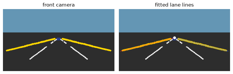
The frame is 180 by 320, with 3 color channels. There are 1426 yellow pixels. Split at column 160.0, the left line has slope -3.942878 and the right line has slope 3.942878. The slopes have opposite signs. The difference is -7.885755.
On row 84, the highest row that still has both lines, the gap is 24.0 pixels. On row 122, down by the bumper, the gap is 298.0 pixels. The near gap is 12.42 times the far gap. The fitted lines meet at column 159.5000, row 82.7753, the white dot.
Nearby paint looks huge, so the near ends are shoved out to the edges of the frame and the far ends shrink toward the middle. Parallel lines meet because of that. The road is not bending.
A planner that treated the pixel gap as the lane width would think the lane was a funnel opening in front of the car. It is not. Before any formula, here is the picture that planner actually wants.
The right-hand picture below is the same road laid flat, in meters. Far is at the top, the way the camera sees the horizon. You do not need the matrix yet.
Predict: each yellow line collapses to one straight stripe, and the gap between the stripes does not change from the near road to the far road.
import json

with (DATA / "calib.json").open(encoding="utf-8") as handle:
    calib = json.load(handle)

x_range = (4.0, 40.0)
y_range = (-10.0, 10.0)
bev_resolution = 0.1
print("forward range m:", f"{x_range[0]:.1f}", f"{x_range[1]:.1f}")
print("lateral range m:", f"{y_range[0]:.1f}", f"{y_range[1]:.1f}")
print("meters per pixel:", f"{bev_resolution:.1f}")

cameras = build_tesla_style_rig(img_w=int(calib["width"]), img_h=int(calib["height"]))
front = cameras["front"]
ipm = IPMTransformer(front, x_range, y_range, bev_resolution)
print("bev height, width:", ipm.bev_height, ipm.bev_width)
print("row 0 forward m:", f"{ipm.bev_pixel_to_metric(0, 0)[0]:.1f}")

lane_y = (5.6, -5.6)
for y_m in lane_y:
    columns = {
        ipm.metric_to_bev_pixel(float(x_m), float(y_m))[0]
        for x_m in np.linspace(6.0, 38.0, 17)
    }
    print(f"lane y {y_m:.1f} columns:", " ".join(str(c) for c in sorted(columns)))
col_left = ipm.metric_to_bev_pixel(20.0, lane_y[0])[0]
col_right = ipm.metric_to_bev_pixel(20.0, lane_y[1])[0]
print("lane columns:", col_left, col_right)
print("separation m:", f"{(col_right - col_left) * bev_resolution:.1f}")

image_seps = []
for x_m in (8.0, 30.0):
    pair = []
    for y_m in lane_y:
        pix, ok = front.project_ego_to_pixel(np.array([x_m, y_m, 0.0]))
        pair.append(float(pix[0, 0]))
        print(
            f"ego x {x_m:.1f} y {y_m:.1f} pixel {pix[0, 0]:.2f} {pix[0, 1]:.2f} valid {bool(ok[0])}"
        )
    sep = abs(pair[1] - pair[0])
    print(f"image separation at x {x_m:.1f}:", f"{sep:.2f}")
    image_seps.append(sep)
print("image separation ratio, near / far:", f"{image_seps[0] / image_seps[1]:.2f}")

bev_bgr = ipm.warp_to_bev(bgr)
bev_rgb = cv2.cvtColor(bev_bgr, cv2.COLOR_BGR2RGB)
print("warp shape height, width, channels:", bev_rgb.shape[0], bev_rgb.shape[1], bev_rgb.shape[2])

yellow_bev = (bev_rgb[:, :, 0] > 180) & (bev_rgb[:, :, 1] > 140) & (bev_rgb[:, :, 2] < 100)
for x_m in (8.0, 36.0):
    row = int(round((x_range[1] - x_m) / bev_resolution))
    cols = np.where(yellow_bev[row])[0]
    left_cols = cols[cols < ipm.bev_width // 2]
    right_cols = cols[cols >= ipm.bev_width // 2]
    print(
        f"paint at forward m {x_m:.1f} row {row} "
        f"width m {((left_cols.max() - left_cols.min()) * bev_resolution):.2f} "
        f"{((right_cols.max() - right_cols.min()) * bev_resolution):.2f}"
    )

keep_inline()
fig, axes = plt.subplots(1, 2, figsize=(8, 3.4))
axes[0].imshow(rgb)
axes[0].set_title("perspective")
axes[0].axis("off")
axes[1].imshow(bev_rgb)
axes[1].set_title("top-down, far at the top")
axes[1].axis("off")
plt.tight_layout()
plt.show()
forward range m: 4.0 40.0
lateral range m: -10.0 10.0
meters per pixel: 0.1
bev height, width: 360 200
row 0 forward m: 40.0
lane y 5.6 columns: 44
lane y -5.6 columns: 156
lane columns: 44 156
separation m: 11.2
ego x 8.0 y 5.6 pixel 74.96 104.85 valid True
ego x 8.0 y -5.6 pixel 245.04 104.85 valid True
image separation at x 8.0: 170.08
ego x 30.0 y 5.6 pixel 141.54 88.17 valid True
ego x 30.0 y -5.6 pixel 178.46 88.17 valid True
image separation at x 30.0: 36.91
image separation ratio, near / far: 4.61
warp shape height, width, channels: 360 200 3
paint at forward m 8.0 row 320 width m 1.20 1.20
paint at forward m 36.0 row 40 width m 6.00 6.00
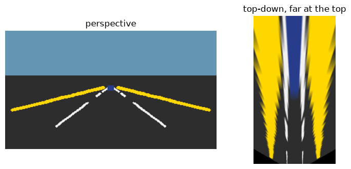
The map is 360 by 200. Row 0 is 40.0 m ahead, and each pixel is 0.1 m. The grid runs from 4.0 m to 40.0 m forward, and from -10.0 m to 10.0 m across.
The lane at 5.6 m is column 44 at every sampled distance. The lane at -5.6 m is column 156. One column each. The gap is 11.2 m, which is 5.6 minus -5.6, and it does not change with range.
In the photo those same two lanes are not a constant gap. At 8.0 m the pixels are column 74.96 and 245.04, both on row 104.85, a gap of 170.08 pixels. At 30.0 m they are column 141.54 and 178.46, both on row 88.17, a gap of 36.91 pixels. The near gap is 4.61 times the far gap. Same 11.2 m of asphalt.
The yellow strokes themselves get fatter with range: 1.20 m of ground at 8.0 m forward, and 6.00 m at 36.0 m. A pixel covers more road when it is far. The geometric lane is one column. The paint is not. A car that measured lane width from the yellow blob would think the lane was getting wider as it looked farther. That is the funnel again, wearing a metric unit.
That top-down picture is the destination. The rest of the notebook peels it apart: why doubling the distance halves the offset, why stretching the photo cannot flatten the road, why one matrix can, and why a nod or a roof wrecks it.
2. Nearby things look big
Same sideways distance, three depths, on a blank frame the size of the photo. The dashed line is the middle column.
Predict: the nearest point sits twice as far from the middle as the middle point, and four times as far as the farthest point.
focal = 100.0
lateral_m = 2.0
principal = 160.0
print("focal px:", f"{focal:.1f}")
print("lateral m:", f"{lateral_m:.1f}")
print("principal column:", f"{principal:.1f}")
for depth in (10.0, 20.0, 40.0):
    offset = focal * lateral_m / depth
    column = offset + principal
    print(f"Z {depth:.0f} offset {offset:.4f} column {column:.4f}")
print("offset ratio Z10 / Z20:", f"{(focal * lateral_m / 10.0) / (focal * lateral_m / 20.0):.1f}")
print("offset ratio Z10 / Z40:", f"{(focal * lateral_m / 10.0) / (focal * lateral_m / 40.0):.1f}")

blank = np.zeros((rgb.shape[0], rgb.shape[1], 3), dtype=np.uint8)
blank[:] = (30, 30, 30)
print("blank frame height, width:", blank.shape[0], blank.shape[1])
keep_inline()
fig, ax = plt.subplots(figsize=(6, 3))
ax.imshow(blank)
ax.axvline(principal, color="white", linewidth=0.6, linestyle="--")
for depth, color in ((10.0, "gold"), (20.0, "deepskyblue"), (40.0, "tomato")):
    column = focal * lateral_m / depth + principal
    ax.scatter([column], [rgb.shape[0] / 2.0], s=40, c=color, label=f"Z={depth:.0f}")
ax.set_xlim(0, rgb.shape[1])
ax.set_ylim(rgb.shape[0], 0)
ax.legend(loc="upper right")
ax.set_title("same lateral offset, three depths")
plt.tight_layout()
plt.show()
focal px: 100.0
lateral m: 2.0
principal column: 160.0
Z 10 offset 20.0000 column 180.0000
Z 20 offset 10.0000 column 170.0000
Z 40 offset 5.0000 column 165.0000
offset ratio Z10 / Z20: 2.0
offset ratio Z10 / Z40: 4.0
blank frame height, width: 180 320
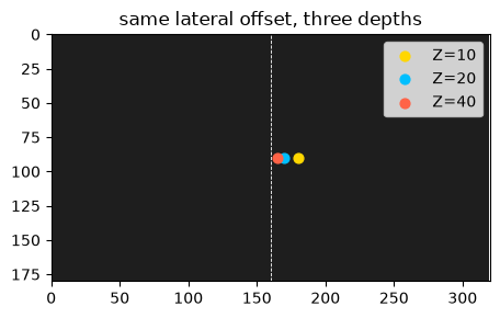
Depth 10 m sits 20.0000 pixels off the middle, at column 180.0000. Depth 20 m sits 10.0000 pixels off, column 170.0000. Depth 40 m sits 5.0000 pixels off, column 165.0000. The ratios are 2.0 and 4.0. The blank frame is the same 180 by 320 as the road photo, so these columns are comparable to the picture above. The middle column is 160.0.
Doubling the distance halved the offset. Hold your thumb at arm's length, then at twice the distance: it covers half as much of the scene. The pixel offset is that thumb. It is the focal length, 100.0, times the sideways meters, 2.0, divided by the depth.
Farther points crowd the middle column. That crowding is why the lane lines meet. A car that used the pixel offset as if it were meters would think a vehicle twice as far was half as wide, and half as far from the lane center. The offset is an angle. Depth is what turns it back into meters.
Try this. Cut the focal length in half and keep the point at depth 10.
Predict: the offset also halves, from 20.0000 pixels to 10.0000.
focal_half = 50.0
offset_half = focal_half * lateral_m / 10.0
print("focal px:", f"{focal_half:.1f}")
print("Z 10 offset:", f"{offset_half:.4f}")
print("offset ratio vs focal 100:", f"{offset_half / 20.0:.1f}")
focal px: 50.0
Z 10 offset: 10.0000
offset ratio vs focal 100: 0.5
Focal length 50.0 puts the same point 10.0000 pixels off center. The ratio versus the 20.0000 pixel offset is 0.5. A shorter lens is a wider view: the same car covers fewer pixels. It does not cancel the divide by depth. Far objects are still small. A wide front camera still needs the top-down map.
3. Stretching the photo fails
An obvious attempt: the far road is squashed toward the horizon, so pull the photo taller until it looks top-down.
Predict: the two slopes stay unequal. The lines still meet at one column. A stretch never divides by depth.
tall = cv2.resize(
    rgb,
    (rgb.shape[1], rgb.shape[0] * 2),
    interpolation=cv2.INTER_NEAREST,
)
print("stretched height, width:", tall.shape[0], tall.shape[1])
print("height ratio:", f"{tall.shape[0] / rgb.shape[0]:.1f}")

yellow_tall = (tall[:, :, 0] > 200) & (tall[:, :, 1] > 150) & (tall[:, :, 2] < 80)
ys_t, xs_t = np.where(yellow_tall)
left_t = xs_t < tall.shape[1] / 2.0
slope_lt, icept_lt = fit_lane_slope(xs_t[left_t], ys_t[left_t])
slope_rt, icept_rt = fit_lane_slope(xs_t[~left_t], ys_t[~left_t])
print("stretched left slope:", f"{slope_lt:.6f}")
print("stretched right slope:", f"{slope_rt:.6f}")
print("stretched slope difference:", f"{slope_lt - slope_rt:.6f}")
v_meet_t = (icept_rt - icept_lt) / (slope_lt - slope_rt)
u_meet_t = slope_lt * v_meet_t + icept_lt
print("stretched vanishing column, row:", f"{u_meet_t:.4f}", f"{v_meet_t:.4f}")
print(
    "|slope difference| ratio, original / stretched:",
    f"{abs(slope_l - slope_r) / abs(slope_lt - slope_rt):.3f}",
)

keep_inline()
fig, axes = plt.subplots(1, 2, figsize=(8, 3.2))
axes[0].imshow(rgb)
axes[0].set_title("original")
axes[0].axis("off")
axes[1].imshow(tall)
axes[1].set_title("height times 2")
axes[1].axis("off")
plt.tight_layout()
plt.show()
stretched height, width: 360 320
height ratio: 2.0
stretched left slope: -1.970265
stretched right slope: 1.970265
stretched slope difference: -3.940529
stretched vanishing column, row: 159.5000 166.0268
|slope difference| ratio, original / stretched: 2.001
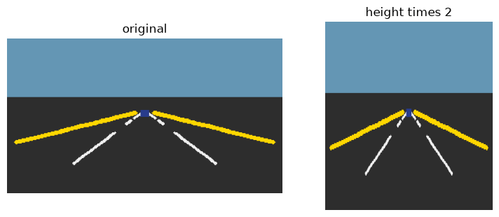
The only change is the height: 360 rows instead of 180, ratio 2.0. Width stays 320.
The slopes become -1.970265 and 1.970265. The difference becomes -3.940529. Its absolute value shrank by 2.001, almost exactly the stretch. The lines still do not share a slope. They still meet, at column 159.5000 and row 166.0268. The column did not move. Every row index was scaled, so the row moved.
Pulling a photograph of a hallway taller does not unbend the hallway. The edges still meet. Perspective is a divide by depth. A resize is not that divide. A car that shipped this picture to a planner would still see a funnel.
4. The lens, in one matrix
The lens is a handful of numbers: how strongly it spreads the view, and which pixel is the middle. Packed into one matrix, they turn a point in front of the lens into a pixel, once you divide by depth at the end.
Predict: with the same round focal length as the last section, a point 2.0 m to the side and 10.0 m deep lands on column 180.0000 again. A matrix written out by hand matches the matrix stored on the camera.
import camera_model as camera_model_module

fx = float(calib["fx"])
fy = float(calib["fy"])
cx = float(calib["cx"])
cy = float(calib["cy"])
print("fx:", f"{fx:.6f}")
print("fy:", f"{fy:.6f}")
print("cx:", f"{cx:.1f}")
print("cy:", f"{cy:.1f}")
print("calib width, height:", int(calib["width"]), int(calib["height"]))

K_hand = np.array(
    [[fx, 0.0, cx], [0.0, fy, cy], [0.0, 0.0, 1.0]],
    dtype=np.float64,
)
print("K shape:", K_hand.shape[0], K_hand.shape[1])
print("K:")
print(np.array2string(K_hand, precision=6, suppress_small=True))
print("max abs diff vs camera.K:", f"{np.max(np.abs(K_hand - front.K)):.6e}")

sol_cam = load_solution("sol_m01_cam_lesson", "camera_model.py")
K_ref = sol_cam.build_intrinsic_matrix(fx, fy, cx, cy)
print("max abs diff vs reference K:", f"{np.max(np.abs(K_hand - K_ref)):.6e}")

try:
    camera_model_module.build_intrinsic_matrix(fx, fy, cx, cy)
    print("module build_intrinsic_matrix: returned")
except NotImplementedError:
    print("module build_intrinsic_matrix: NotImplementedError")

point_cam = np.array([2.0, 1.0, 10.0])
print("camera-frame point:", " ".join(f"{v:.1f}" for v in point_cam))
K_toy = np.array(
    [[focal, 0.0, principal], [0.0, focal, cy], [0.0, 0.0, 1.0]],
    dtype=np.float64,
)
print("toy focal, principal column, principal row:", f"{focal:.1f}", f"{principal:.1f}", f"{cy:.1f}")
multiplied = K_toy @ point_cam
print("K @ point:", " ".join(f"{v:.4f}" for v in multiplied))
print("third component:", f"{multiplied[2]:.4f}")
u_toy = multiplied[0] / multiplied[2]
v_toy = multiplied[1] / multiplied[2]
print("pixel column, row:", f"{u_toy:.4f}", f"{v_toy:.4f}")
print("column offset from principal:", f"{u_toy - principal:.4f}")
fx: 92.376043
fy: 92.376043
cx: 160.0
cy: 90.0
calib width, height: 320 180
K shape: 3 3
K:
[[ 92.376043   0.       160.      ]
 [  0.        92.376043  90.      ]
 [  0.         0.         1.      ]]
max abs diff vs camera.K: 0.000000e+00
max abs diff vs reference K: 0.000000e+00
module build_intrinsic_matrix: NotImplementedError
camera-frame point: 2.0 1.0 10.0
toy focal, principal column, principal row: 100.0 160.0 90.0
K @ point: 1800.0000 1000.0000 10.0000
third component: 10.0000
pixel column, row: 180.0000 100.0000
column offset from principal: 20.0000
The sample front camera has focal lengths 92.376043 and 92.376043, middle pixel (160.0, 90.0), on a 320 by 180 image. The matrix is 3 by 3. The hand-built one matches the camera and the reference, both with max absolute difference 0.000000e+00.
The function the tests import from camera_model.py still raises NotImplementedError. The class does not call it. It writes the same nine numbers itself. The exercise is that function.
For the toy point (2.0, 1.0, 10.0), with focal length 100.0 and middle row 90.0, the product is 1800.0000 1000.0000 10.0000. The third entry is the depth, 10.0000. Dividing gives column 180.0000 and row 100.0000. The column offset is 20.0000, the same offset as the depth-10 point on the blank frame. The matrix did not invent a new geometry. It is "scale by the focal length, add the middle pixel, and remember to divide by depth," written so one multiply can do it.
A calibration file is this matrix plus where the camera is bolted on. Get the matrix wrong and every later meter is wrong in the same direction.
Exercise — build_intrinsic_matrix. Return the 3 by 3 matrix from fx, fy, cx, and cy. Focal lengths on the diagonal, the middle pixel in the last column, a one in the corner. Leave the TODO as it is to use the reference implementation.
def build_intrinsic_matrix_student(fx_value, fy_value, cx_value, cy_value):
    # TODO: return the 3x3 intrinsic matrix
    raise NotImplementedError

def get_intrinsic_fn():
    try:
        build_intrinsic_matrix_student(1.0, 1.0, 0.0, 0.0)
    except NotImplementedError:
        print("Using reference build_intrinsic_matrix (TODO not implemented)")
        return sol_cam.build_intrinsic_matrix
    print("Using your build_intrinsic_matrix")
    return build_intrinsic_matrix_student

intrinsic_fn = get_intrinsic_fn()
K_check = intrinsic_fn(front.fx, front.fy, front.cx, front.cy)
intrinsic_diff = float(np.max(np.abs(K_check - front.K)))
print("max abs diff vs camera.K:", f"{intrinsic_diff:.6e}")
assert K_check.shape == (3, 3)
assert intrinsic_diff < 1e-9
print("✅ correct")
Using reference build_intrinsic_matrix (TODO not implemented)
max abs diff vs camera.K: 0.000000e+00
✅ correct
The reference matrix is in use, because the TODO still raises. The largest gap versus the camera's own matrix is 0.000000e+00. Replace the TODO and the same check calls your function.
Solution
def build_intrinsic_matrix(fx, fy, cx, cy):
    return np.array(
        [[fx, 0.0, cx], [0.0, fy, cy], [0.0, 0.0, 1.0]],
        dtype=float,
    )
5. Where the camera is bolted
A rotation turns a vector and does not change its length. In the plane, a quarter turn counterclockwise swings the horizontal axis up onto the vertical axis.
Predict: a point that sits on the horizontal axis lands on the vertical axis, and its distance from the origin does not change.
theta_deg = 90.0
theta = np.deg2rad(theta_deg)
rotation_2d = np.array(
    [[np.cos(theta), -np.sin(theta)], [np.sin(theta), np.cos(theta)]],
    dtype=np.float64,
)
point_2d = np.array([4.0, 0.0])
rotated = rotation_2d @ point_2d
print("theta degrees:", f"{theta_deg:.1f}")
print("input x, y:", f"{point_2d[0]:.1f}", f"{point_2d[1]:.1f}")
print("rotated x, y:", f"{rotated[0]:.4f}", f"{rotated[1]:.4f}")

keep_inline()
fig, ax = plt.subplots(figsize=(3.4, 3.4))
ax.annotate("", xy=(point_2d[0], point_2d[1]), xytext=(0, 0),
            arrowprops=dict(arrowstyle="-|>", color="0.45", lw=1.6))
ax.annotate("", xy=(rotated[0], rotated[1]), xytext=(0, 0),
            arrowprops=dict(arrowstyle="-|>", color="#d4654f", lw=1.6))
ax.scatter([point_2d[0], rotated[0]], [point_2d[1], rotated[1]], c=["0.45", "#d4654f"], zorder=3)
ax.set_xlim(-0.5, 5)
ax.set_ylim(-0.5, 5)
ax.set_aspect("equal")
ax.set_xlabel("x")
ax.set_ylabel("y")
ax.set_title("a quarter turn")
plt.tight_layout()
plt.show()
theta degrees: 90.0
input x, y: 4.0 0.0
rotated x, y: 0.0000 4.0000
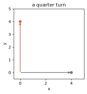
90.0 degrees sends (4.0, 0.0) to (0.0000, 4.0000). The gray arrow that pointed along the ground now points up, in red. The length is still 4.0. A camera does this in three dimensions, then slides the origin: a point on the car becomes a point in front of the lens by P_cam = R @ P_ego + T.
The car and the camera do not share axis names.
Ego, for the rest of this course: forward, left, up. The origin is on the ground at the rear axle. Camera: right, down, and out through the lens.
Z up
  |
  |     camera * ----> look direction
  |    /
  |   /   pitched down
  +--------> forward
 rear axle
Predict: with no tilt, ego forward becomes the look direction. Ego left becomes negative camera-right. Ego up becomes negative camera-down. The real camera is tilted, so a point on the centerline of the road is not on the middle row of the image.
axis_change = np.array(
    [[0.0, -1.0, 0.0], [0.0, 0.0, -1.0], [1.0, 0.0, 0.0]],
    dtype=np.float64,
)

def fmt(vec):
    return " ".join(f"{v:.1f}" for v in np.asarray(vec, dtype=np.float64))

print("ego forward -> camera:", fmt(axis_change @ np.array([1.0, 0.0, 0.0])))
print("ego left -> camera:", fmt(axis_change @ np.array([0.0, 1.0, 0.0])))
print("ego up -> camera:", fmt(axis_change @ np.array([0.0, 0.0, 1.0])))

print("pitch deg:", f"{float(calib['pitch_deg']):.1f}")
print("yaw deg:", f"{float(calib['yaw_deg']):.1f}")
print("roll deg:", f"{float(calib['roll_deg']):.1f}")
cam_pos = np.array(calib["cam_position_ego"], dtype=np.float64)
print("camera position ego x, y, z:", fmt(cam_pos))

R_ego = create_euler_rotation(
    float(calib["pitch_deg"]), float(calib["yaw_deg"]), float(calib["roll_deg"])
)
T_ego = camera_position_to_translation(R_ego, cam_pos).reshape(3)
print("T x, y, z:", " ".join(f"{v:.6f}" for v in T_ego))
print("max abs diff vs camera.T:", f"{np.max(np.abs(T_ego - front.T.reshape(3))):.6e}")
print("max abs diff vs camera.R:", f"{np.max(np.abs(R_ego - front.R)):.6e}")

def project_chain(point_ego):
    point_cam = front.R @ point_ego + front.T.reshape(3)
    scaled = front.K @ point_cam
    pixel = scaled[:2] / scaled[2]
    repo_px, valid = front.project_ego_to_pixel(point_ego)
    print("ego x, y, z:", " ".join(f"{v:.6f}" for v in point_ego))
    print("P_cam x, y, z:", " ".join(f"{v:.6f}" for v in point_cam))
    print("K @ P_cam:", " ".join(f"{v:.6f}" for v in scaled))
    print("divide by Z_cam:", f"{scaled[2]:.6f}")
    print("pixel column, row:", f"{pixel[0]:.6f}", f"{pixel[1]:.6f}")
    print("project_ego_to_pixel:", f"{repo_px[0, 0]:.6f}", f"{repo_px[0, 1]:.6f}", "valid", bool(valid[0]))
    print(
        "pixel diff column, row:",
        f"{pixel[0] - repo_px[0, 0]:.6f}",
        f"{pixel[1] - repo_px[0, 1]:.6f}",
    )
    return pixel

print("--- point on the centerline ---")
px_center = project_chain(np.array([10.0, 0.0, 0.0]))
print("--- point 1 m to the left ---")
px_left = project_chain(np.array([20.0, 1.0, 0.0]))

keep_inline()
fig, ax = plt.subplots(figsize=(6, 3.2))
ax.imshow(rgb)
ax.scatter([px_center[0]], [px_center[1]], c="white", s=36, label="10 m, center")
ax.scatter([px_left[0]], [px_left[1]], c="#d4654f", s=36, label="20 m, 1 m left")
ax.axvline(cx, color="white", linewidth=0.5, linestyle="--")
ax.legend(loc="lower right", fontsize=8)
ax.set_title("two ground points on the photo")
ax.axis("off")
plt.tight_layout()
plt.show()
ego forward -> camera: 0.0 0.0 1.0
ego left -> camera: -1.0 0.0 0.0
ego up -> camera: 0.0 -1.0 0.0
pitch deg: 4.0
yaw deg: 0.0
roll deg: 0.0
camera position ego x, y, z: 2.0 0.0 1.4
T x, y, z: 0.000000 1.536103 -1.897469
max abs diff vs camera.T: 0.000000e+00
max abs diff vs camera.R: 0.000000e+00
--- point on the centerline ---
ego x, y, z: 10.000000 0.000000 0.000000
P_cam x, y, z: 0.000000 0.838538 8.078171
K @ P_cam: 1292.507434 804.496243 8.078171
divide by Z_cam: 8.078171
pixel column, row: 160.000000 99.588904
project_ego_to_pixel: 160.000000 99.588904 valid True
pixel diff column, row: 0.000000 0.000000
--- point 1 m to the left ---
ego x, y, z: 20.000000 1.000000 0.000000
P_cam x, y, z: -1.000000 0.140973 18.053812
K @ P_cam: 2796.233872 1637.865618 18.053812
divide by Z_cam: 18.053812
pixel column, row: 154.883294 90.721318
project_ego_to_pixel: 154.883294 90.721318 valid True
pixel diff column, row: 0.000000 0.000000
With no tilt, ego forward becomes camera 0.0 0.0 1.0, straight out the lens. Ego left becomes -1.0 0.0 0.0. Ego up becomes 0.0 -1.0 0.0. Left in the car is right-negative in the image. Up in the car is down-negative in the image. That swap is why a point to the car's left moves to a smaller column.
The real front camera is not that ideal pose. It sits 2.0 m forward, 0.0 m to the side, and 1.4 m up, pitched down 4.0 degrees. Yaw and roll are 0.0. Translation comes out 0.000000 1.536103 -1.897469. Rotation and translation both match the camera object, max absolute difference 0.000000e+00.
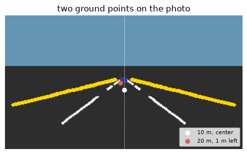
The ground point 10.000000 m ahead on the centerline arrives in the camera as (0.000000, 0.838538, 8.078171). It is neither left nor right of the lens. It sits below the optical axis, because the road is under a camera that looks slightly down. The depth along the lens is 8.078171 m, not 10.000000, because the camera is already 2.0 m forward of the rear axle and the pitch tilts the axis. K times that point is 1292.507434 804.496243 8.078171. Dividing by 8.078171 lands on pixel (160.000000, 99.588904). The column is the middle. The row is below the middle row 90.0. The long chain and project_ego_to_pixel differ by 0.000000 and 0.000000. The white dot in the picture is that point.
The point 20.000000 m ahead and 1.000000 m to the left has camera X of -1.000000 and depth 18.053812. It lands on (154.883294, 90.721318), the red dot, left of column 160.000000. That is the image of "left" after the axes have been swapped.
A car that swapped left and right here would steer toward the obstacle. The axis change is the difference between a correction and a yank.
6. A flat road is one 3 by 3
Assume the point is on the ground. Its height is 0.000000, the value already printed for the centerline point. One column of the rotation multiplies that height and drops out. What is left is a single 3 by 3 matrix from ground meters to pixels.
Predict: the centerline ground point comes back to pixel (160.000000, 99.588904), the same pixel as the long chain. Sending that pixel back through the inverse returns 10.000000 m, up to rounding.
r1 = front.R[:, 0:1]
r2 = front.R[:, 1:2]
t_col = front.T.reshape(3, 1)
H = front.K @ np.hstack([r1, r2, t_col])
print("H shape:", H.shape[0], H.shape[1])

sol_ipm = load_solution("sol_m01_ipm_lesson", "ipm.py")
H_ref = sol_ipm.build_ground_homography(front.K, front.R, front.T)
print("max abs diff vs reference H:", f"{np.max(np.abs(H - H_ref)):.6e}")

ground = np.array([10.0, 0.0, 1.0])
q = H @ ground
uv = q[:2] / q[2]
print("H @ (10, 0, 1) before divide:", " ".join(f"{v:.6f}" for v in q))
print("homography pixel column, row:", f"{uv[0]:.6f}", f"{uv[1]:.6f}")
chain_px, chain_ok = front.project_ego_to_pixel(np.array([10.0, 0.0, 0.0]))
print("chain pixel column, row:", f"{chain_px[0, 0]:.6f}", f"{chain_px[0, 1]:.6f}")
print(
    "pixel diff column, row:",
    f"{uv[0] - chain_px[0, 0]:.6e}",
    f"{uv[1] - chain_px[0, 1]:.6e}",
)

back = np.linalg.inv(H) @ np.array([uv[0], uv[1], 1.0])
xy = back[:2] / back[2]
round_err = float(np.linalg.norm(xy - np.array([10.0, 0.0])))
print("inverse X, Y:", f"{xy[0]:.6f}", f"{xy[1]:.6e}")
print("round-trip error m:", f"{round_err:.3e}")

pixel_errs = []
for x_m, y_m in ((10.0, 0.0), (20.0, 1.0), (30.0, -1.5)):
    q_i = H @ np.array([x_m, y_m, 1.0])
    uv_i = q_i[:2] / q_i[2]
    pix_i, _ = front.project_ego_to_pixel(np.array([x_m, y_m, 0.0]))
    pixel_errs.append(float(np.hypot(uv_i[0] - pix_i[0, 0], uv_i[1] - pix_i[0, 1])))
print("max pixel error on 3 ground points:", f"{max(pixel_errs):.6e}")
H shape: 3 3
max abs diff vs reference H: 0.000000e+00
H @ (10, 0, 1) before divide: 1292.507434 804.496243 8.078171
homography pixel column, row: 160.000000 99.588904
chain pixel column, row: 160.000000 99.588904
pixel diff column, row: 0.000000e+00 0.000000e+00
inverse X, Y: 10.000000 1.793714e-15
round-trip error m: 5.623e-15
max pixel error on 3 ground points: 3.177644e-14
The matrix is 3 by 3. It matches the reference with max absolute difference 0.000000e+00.
It sends (10, 0, 1) to 1292.507434 804.496243 8.078171, and dividing lands on pixel (160.000000, 99.588904). The difference versus the long chain is 0.000000e+00 in both column and row. The inverse brings back X = 10.000000 and a Y of 1.793714e-15. The round trip misses by 5.623e-15 meters. That is rounding, not a bias.
On three ground points the worst disagreement with project_ego_to_pixel is 3.177644e-14 pixels. On flat ground this matrix is not a sketch of the pinhole. It is the pinhole with the ground height filled in.
Write it H = K @ [r1 r2 t]. r1 and r2 are the first two columns of the rotation. t is the translation. A flat road is what lets one 3 by 3 undo the perspective in the first picture. The top-down map you already saw walks a meter grid and copies the color each cell projects to. On the ground, that projection is this matrix.
A curb, a speed bump, a car with a roof: anything off the plane, and the dropped column was not zero. The last sections measure that lie.
Exercise — build_ground_homography. Return H = K @ [r1 r2 t] for a ground plane at height 0. t may arrive as shape (3,) or (3, 1). Leave the TODO as it is to use the reference implementation.
def build_ground_homography_student(K_value, R_value, t_value):
    # TODO: H = K @ [r1 r2 t] for the ground plane
    raise NotImplementedError

def get_homography_fn():
    try:
        build_ground_homography_student(front.K, front.R, front.T)
    except NotImplementedError:
        print("Using reference build_ground_homography (TODO not implemented)")
        return sol_ipm.build_ground_homography
    print("Using your build_ground_homography")
    return build_ground_homography_student

homography_fn = get_homography_fn()
H_check = homography_fn(front.K, front.R, front.T)
check_errs = []
for x_m, y_m in ((10.0, 0.0), (20.0, 1.0), (30.0, -1.5)):
    q_i = H_check @ np.array([x_m, y_m, 1.0])
    uv_i = q_i[:2] / q_i[2]
    pix_i, valid_i = front.project_ego_to_pixel(np.array([x_m, y_m, 0.0]))
    err_i = float(np.hypot(uv_i[0] - pix_i[0, 0], uv_i[1] - pix_i[0, 1]))
    check_errs.append(err_i)
    print(
        f"ground {x_m:.1f} {y_m:.1f} pixel error {err_i:.6e} valid {bool(valid_i[0])}"
    )
print("max pixel error:", f"{max(check_errs):.6e}")
tolerance_px = 1e-3
print("pixel tolerance:", f"{tolerance_px:.0e}")
assert max(check_errs) < tolerance_px
print("✅ correct")
Using reference build_ground_homography (TODO not implemented)
ground 10.0 0.0 pixel error 0.000000e+00 valid True
ground 20.0 1.0 pixel error 0.000000e+00 valid True
ground 30.0 -1.5 pixel error 3.177644e-14 valid True
max pixel error: 3.177644e-14
pixel tolerance: 1e-03
✅ correct
The reference matrix is in use, because the TODO still raises. The largest pixel error against project_ego_to_pixel is 3.177644e-14, under the tolerance 1e-03. The ground point at 30.0 m and -1.5 m is the one that shows that rounding. The other two points differ by 0.000000e+00. Replace the TODO and the same check calls your function.
Solution
def build_ground_homography(K, R, t):
    t_vec = np.asarray(t, dtype=float).reshape(3, 1)
    return K @ np.hstack([R[:, 0:2], t_vec])
7. Three cameras, still one map
One forward camera looks ahead. It misses ground close to the bumper, off to either side. The folder has a left camera and a right camera, each turned outward. They land on the same meter grid. Where more than one camera sees a cell, the colors are averaged.
Predict: the stitched picture covers this whole grid. The cells the front camera leaves black are near the bumper and out to the sides.
frames = {}
for name in ("front", "left", "right"):
    frames[name] = cv2.imread(str(DATA / f"{name}.png"))
    print(f"{name} height, width:", frames[name].shape[0], frames[name].shape[1])

stitched = stitch_three_cameras(frames, cameras, x_range, y_range, bev_resolution)
print("stitched height, width:", stitched.shape[0], stitched.shape[1])

def coverage(image):
    return float(np.any(image > 0, axis=-1).mean())

print("front coverage:", f"{coverage(bev_bgr):.4f}")
print("stitched coverage:", f"{coverage(stitched):.4f}")
front_on = np.any(bev_bgr > 0, axis=-1)
stitched_on = np.any(stitched > 0, axis=-1)
added = stitched_on & ~front_on
added_rows, added_cols = np.where(added)
added_x = x_range[1] - added_rows * bev_resolution
added_y = y_range[1] - added_cols * bev_resolution
print("cells only the side cameras color:", int(added.sum()))
print("those cells, forward m min max:", f"{added_x.min():.1f}", f"{added_x.max():.1f}")
print("those cells with |lateral| > 6 m:", int(np.sum(np.abs(added_y) > 6.0)))

weight = np.zeros(front_on.shape, dtype=np.int32)
for name in ("front", "left", "right"):
    view = IPMTransformer(cameras[name], x_range, y_range, bev_resolution)
    weight += view.valid_mask.astype(np.int32)
print("max cameras on one cell:", int(weight.max()))
print("cells seen by 2 or more:", int(np.sum(weight >= 2)))
print("cells seen by all 3:", int(np.sum(weight == 3)))
print("cells seen by exactly 1:", int(np.sum(weight == 1)))

keep_inline()
fig, axes = plt.subplots(1, 2, figsize=(8, 3.4))
axes[0].imshow(bev_rgb)
axes[0].set_title("front only")
axes[0].axis("off")
axes[1].imshow(cv2.cvtColor(stitched, cv2.COLOR_BGR2RGB))
axes[1].set_title("front + left + right")
axes[1].axis("off")
plt.tight_layout()
plt.show()
front height, width: 180 320
left height, width: 180 320
right height, width: 180 320
stitched height, width: 360 200
front coverage: 0.9682
stitched coverage: 1.0000
cells only the side cameras color: 2292
those cells, forward m min max: 4.1 7.6
those cells with |lateral| > 6 m: 1974
max cameras on one cell: 3
cells seen by 2 or more: 69278
cells seen by all 3: 7276
cells seen by exactly 1: 2722
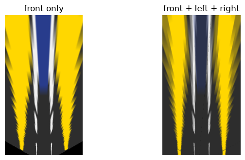
All three frames are 180 by 320. The stitched map is the same 360 by 200 grid.
Front coverage is 0.9682. Stitched coverage is 1.0000. The side cameras color 2292 cells the front warp left black. Those cells sit between 4.1 m and 7.6 m forward, and 1974 of them are more than 6 m off the centerline. That is the near corner beside the bumper, where a forward camera is looking over the road rather than at it.
The busiest cell is seen by 3 cameras. 69278 cells are seen by two or more, 7276 by all three, and 2722 by exactly one. Where the views overlap, the stitch averages. On this drawing the cameras agree, so the average looks like one road. On a real car, a bad bolt-on angle shows up there as a doubled lane line.
A car that trusted only the front warp would be blind in those 2292 cells. A person standing just ahead of the front wheel can live in that patch.
8. One degree of tilt
The matrix trusts the pitch of the camera. Suppose the camera is a degree more nose-down than the file says. You still see the true pixel of a ground point. You then intersect that pixel with the ground using the wrong pitch. The number below is estimated forward distance minus the true forward distance.
Predict: no extra pitch is a numerical zero. One extra degree is a modest miss nearby and a much larger miss far away. The miss grows faster than the distance.
def range_error(calib_dict, delta_deg, range_m):
    width = int(calib_dict["width"])
    height = int(calib_dict["height"])
    position = np.array(calib_dict["cam_position_ego"], dtype=np.float64)
    pitch = float(calib_dict["pitch_deg"])
    yaw = float(calib_dict["yaw_deg"])
    roll = float(calib_dict["roll_deg"])
    rotation_true = create_euler_rotation(pitch, yaw, roll)
    translation_true = camera_position_to_translation(rotation_true, position)
    true_cam = PinholeCamera(
        "true", calib_dict["fx"], calib_dict["fy"], calib_dict["cx"], calib_dict["cy"],
        width, height, rotation_true, translation_true,
    )
    pixel, valid = true_cam.project_ego_to_pixel(np.array([[range_m, 0.0, 0.0]]))
    if not valid[0]:
        return 0.0
    rotation_bias = create_euler_rotation(pitch + delta_deg, yaw, roll)
    translation_bias = camera_position_to_translation(rotation_bias, position)
    bias_cam = PinholeCamera(
        "bias", calib_dict["fx"], calib_dict["fy"], calib_dict["cx"], calib_dict["cy"],
        width, height, rotation_bias, translation_bias,
    )
    estimated, ok = bias_cam.project_pixels_to_ground(pixel)
    if not ok[0]:
        return 0.0
    return float(estimated[0, 0] - range_m)

delta_deg = 1.0
print("extra pitch deg:", f"{delta_deg:.1f}")
ranges = np.array([10.0, 20.0, 30.0, 40.0])
errors = np.array([range_error(calib, delta_deg, float(distance)) for distance in ranges])
print("range_m  error_m  estimated_m")
for distance, error in zip(ranges, errors):
    print(f"{distance:.0f}  {error:.4f}  {distance + error:.4f}")
print("abs error ratio 40 m / 10 m:", f"{abs(errors[-1] / errors[0]):.2f}")
print("distance ratio 40 m / 10 m:", f"{ranges[-1] / ranges[0]:.1f}")
zero_error = range_error(calib, 0.0, 20.0)
print("extra pitch 0 at 20 m:", f"{zero_error:.3e}")

sol_pitch = load_solution("sol_m01_pitch_lesson", "pitch_sensitivity.py")
ref_40 = sol_pitch.pitch_shift_meters(calib, delta_deg, 40.0)
print("reference pitch_shift_meters at 40 m:", f"{ref_40:.4f}")
print("diff vs table at 40 m:", f"{abs(ref_40 - errors[-1]):.3e}")

keep_inline()
fig, ax = plt.subplots(figsize=(6, 3.4))
ax.plot(ranges, errors, marker="o", color="#d4654f")
ax.axhline(0.0, color="gray", linewidth=0.8)
ax.set_xlabel("true forward distance (m)")
ax.set_ylabel("estimated minus true (m)")
ax.set_title("one extra degree, nose down")
plt.tight_layout()
plt.show()
extra pitch deg: 1.0
range_m  error_m  estimated_m
10  -0.7478  9.2522
20  -3.3191  16.6809
30  -7.2636  22.7364
40  -12.2325  27.7675
abs error ratio 40 m / 10 m: 16.36
distance ratio 40 m / 10 m: 4.0
extra pitch 0 at 20 m: -1.421e-14
reference pitch_shift_meters at 40 m: -12.2325
diff vs table at 40 m: 0.000e+00
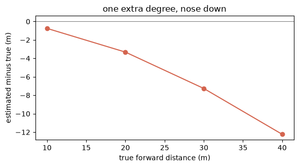
With 0 extra degrees, the error at 20 m is -1.421e-14. Roundoff. The calibration, used on itself, returns the true distance.
With 1.0 extra degree of nose-down pitch, a point at 10 m is read as 9.2522 m, error -0.7478 m. At 20 m the error is -3.3191 m, so the map says 16.6809 m. At 30 m the error is -7.2636 m, and the map says 22.7364 m. At 40 m the map says 27.7675 m, error -12.2325 m.
The distance grew by a factor of 4.0. The absolute error grew by a factor of 16.36. A rifle sight that is a degree off is a miss of inches nearby and a miss of many feet at range. This is that lever, pointed at the road. The reference function agrees at 40 m: difference 0.000e+00. The curve bends down. It is not a straight line through the origin.
The sign is negative. The map pulls the point toward the bumper. A lead car at 40 m is reported at 27.7675 m. The brake comes early, for a gap that is still open. One degree is a nod a hard stop can give the nose. It is not a small error at range.
Exercise — pitch_shift_meters. Given the calibration dict, an extra pitch in degrees, and a true forward distance, return estimated forward distance minus the true distance. Use the same camera the table just used. Leave the TODO as it is to use the reference implementation.
The check wants a numerical zero when the extra pitch is 0, and a larger absolute error at 40 m than at 10 m when the extra pitch is 1.0 degree.
def pitch_shift_meters_student(calib_dict, delta_deg_value, range_m):
    # TODO: estimated forward distance minus range_m
    raise NotImplementedError

def get_pitch_fn():
    try:
        pitch_shift_meters_student(calib, 0.0, 20.0)
    except NotImplementedError:
        print("Using reference pitch_shift_meters (TODO not implemented)")
        return sol_pitch.pitch_shift_meters
    print("Using your pitch_shift_meters")
    return pitch_shift_meters_student

pitch_fn = get_pitch_fn()
err_zero = pitch_fn(calib, 0.0, 20.0)
err_10 = pitch_fn(calib, 1.0, 10.0)
err_40 = pitch_fn(calib, 1.0, 40.0)
print("delta 0 deg at 20 m:", f"{err_zero:.3e}")
print("delta 1 deg at 10 m:", f"{err_10:.4f}")
print("delta 1 deg at 40 m:", f"{err_40:.4f}")
assert abs(err_zero) < 1e-2
assert abs(err_40) > abs(err_10)
assert abs(err_10 - errors[0]) < 1e-6
assert abs(err_40 - errors[-1]) < 1e-6
print("✅ correct")
Using reference pitch_shift_meters (TODO not implemented)
delta 0 deg at 20 m: -1.421e-14
delta 1 deg at 10 m: -0.7478
delta 1 deg at 40 m: -12.2325
✅ correct
The reference function is in use, because the TODO still raises. Extra pitch 0 at 20 m returns -1.421e-14. Extra pitch 1.0 degree returns -0.7478 m at 10 m and -12.2325 m at 40 m, the same misses as the plot. The miss at 40 m is the larger one. Replace the TODO and the same check calls your function.
Solution
Project the true ground point with the file's pitch. Intersect that pixel with the ground again, using the pitch plus delta_deg. Return the estimated forward distance minus range_m.
def pitch_shift_meters(calib, delta_deg, range_m):
    width = int(calib["width"])
    height = int(calib["height"])
    position = np.array(calib["cam_position_ego"], dtype=float)
    pitch = float(calib["pitch_deg"])
    yaw = float(calib["yaw_deg"])
    roll = float(calib["roll_deg"])
    rotation_true = create_euler_rotation(pitch, yaw, roll)
    translation_true = camera_position_to_translation(rotation_true, position)
    true_cam = PinholeCamera(
        "true", calib["fx"], calib["fy"], calib["cx"], calib["cy"],
        width, height, rotation_true, translation_true,
    )
    pixel, valid = true_cam.project_ego_to_pixel(np.array([[range_m, 0.0, 0.0]]))
    if not valid[0]:
        return 0.0
    rotation_bias = create_euler_rotation(pitch + delta_deg, yaw, roll)
    translation_bias = camera_position_to_translation(rotation_bias, position)
    bias_cam = PinholeCamera(
        "bias", calib["fx"], calib["fy"], calib["cx"], calib["cy"],
        width, height, rotation_bias, translation_bias,
    )
    estimated, ok = bias_cam.project_pixels_to_ground(pixel)
    if not ok[0]:
        return 0.0
    return float(estimated[0, 0] - range_m)
9. A raised car smears
The second break is the ground itself. The drawing puts a lead vehicle at one forward distance, wheels on the road, roof above it. The map treats every pixel as a floor pixel. A point above the road is shoved to wherever that ray eventually hits the asphalt.
Predict: the point on the road under the vehicle stays at its true distance. A point partway up the vehicle is placed much farther away. The roof is above the camera, so that ray never hits the road in front of the car. In the top-down image the vehicle color is smeared forward, not parked on its footprint.
box = np.array(
    [
        [22.0, -0.9, 0.0],
        [22.0, 0.9, 0.0],
        [22.0, 0.9, 1.5],
        [22.0, -0.9, 1.5],
    ],
    dtype=np.float64,
)
print("box forward m, all corners:", " ".join(f"{v:.1f}" for v in box[:, 0]))
print("box lateral m min max:", f"{box[:, 1].min():.1f}", f"{box[:, 1].max():.1f}")
print("box height m min max:", f"{box[:, 2].min():.1f}", f"{box[:, 2].max():.1f}")
print("camera height m:", f"{cam_pos[2]:.1f}")

landed_h = []
landed_x = []
for height in (0.0, 0.5, 1.0, 1.5):
    point = np.array([[22.0, 0.0, height]])
    pixel, valid = front.project_ego_to_pixel(point)
    estimated, hit = front.project_pixels_to_ground(pixel)
    print(
        f"height m {height:.1f} pixel row {pixel[0, 1]:.2f} "
        f"valid {bool(valid[0])} ground hit {bool(hit[0])}"
    )
    if hit[0]:
        print(
            f"  ground forward m {estimated[0, 0]:.3f} "
            f"shift m {estimated[0, 0] - 22.0:.3f}"
        )
        landed_h.append(height)
        landed_x.append(float(estimated[0, 0]))

car = (
    (bev_bgr[:, :, 0] > 100)
    & (bev_bgr[:, :, 0] < 180)
    & (bev_bgr[:, :, 1] < 90)
    & (bev_bgr[:, :, 2] < 70)
)
car_image = (
    (bgr[:, :, 0] > 100)
    & (bgr[:, :, 0] < 180)
    & (bgr[:, :, 1] < 90)
    & (bgr[:, :, 2] < 70)
)
print("car pixels in the camera image:", int(car_image.sum()))
print("car pixels in the front BEV:", int(car.sum()))
car_rows, car_cols = np.where(car)
car_x = x_range[1] - car_rows * bev_resolution
car_y = y_range[1] - car_cols * bev_resolution
print("BEV car forward m min max:", f"{car_x.min():.1f}", f"{car_x.max():.1f}")
print("BEV car lateral m min max:", f"{car_y.min():.1f}", f"{car_y.max():.1f}")
footprint_row = int(round((x_range[1] - 22.0) / bev_resolution))
print("true footprint forward m:", f"{22.0:.1f}")
print("true footprint bev row:", footprint_row)

keep_inline()
fig, axes = plt.subplots(1, 3, figsize=(10, 3.2))
axes[0].imshow(rgb)
for height, color in ((0.0, "white"), (1.5, "#d4654f")):
    corners = np.array([[22.0, -0.9, height], [22.0, 0.9, height]])
    pix, _ = front.project_ego_to_pixel(corners)
    axes[0].plot(pix[:, 0], pix[:, 1], color=color, marker="o", linewidth=1.2)
axes[0].set_title("box on the photo")
axes[0].axis("off")

axes[1].imshow(bev_rgb)
axes[1].axhline(footprint_row, color="white", linewidth=0.8)
axes[1].set_title("top-down smear")
axes[1].axis("off")

axes[2].plot(landed_h, landed_x, marker="o", color="#d4654f")
axes[2].axhline(22.0, color="gray", linewidth=0.8)
axes[2].set_xlabel("height of the point (m)")
axes[2].set_ylabel("where the flat map puts it (m)")
axes[2].set_title("raised points thrown forward")
plt.tight_layout()
plt.show()
box forward m, all corners: 22.0 22.0 22.0 22.0
box lateral m min max: -0.9 0.9
box height m min max: 0.0 1.5
camera height m: 1.4
height m 0.0 pixel row 90.01 valid True ground hit True
  ground forward m 22.000 shift m -0.000
height m 0.5 pixel row 87.70 valid True ground hit True
  ground forward m 33.111 shift m 11.111
height m 1.0 pixel row 85.39 valid True ground hit True
  ground forward m 72.000 shift m 50.000
height m 1.5 pixel row 83.08 valid True ground hit False
car pixels in the camera image: 80
car pixels in the front BEV: 5543
BEV car forward m min max: 20.9 40.0
BEV car lateral m min max: -1.7 2.1
true footprint forward m: 22.0
true footprint bev row: 180
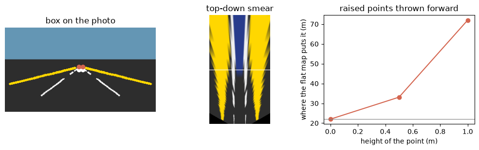
Every corner of the box is at 22.0 m. Laterally it runs from -0.9 m to 0.9 m. The roof is at 1.5 m and the camera is at 1.4 m, so the roof is above the lens. The white line in the middle picture is that footprint, top-down row 180.
The road point, height 0.0, is pixel row 90.01 and comes back to 22.000 m. Shift -0.000 m. Height 0.5 m is pixel row 87.70 and is placed at 33.111 m, a shift of 11.111 m. Height 1.0 m is pixel row 85.39 and lands at 72.000 m, a shift of 50.000 m, already past the 40.0 m edge of this grid. Height 1.5 m is a real pixel, row 83.08, and the ground hit is false: the ray from a camera at 1.4 m through a point at 1.5 m is going up.
The camera image contains 80 vehicle pixels. The top-down map contains 5543 pixels of that color, from 20.9 m to 40.0 m forward and from -1.7 m to 2.1 m laterally. The right-hand plot is the same fact without the picture: lift the point off the floor and the flat map throws it forward. The gray line is the true 22.0 m. The red curve leaves it immediately.
Distant ground cells look up and see the side of the car, the way a long shadow at sunset is not the person. The car is smeared out to the far edge of the map. Its true footprint was one distance. A pedestrian does the same thing. Lane paint, which really is on the road, does not. The 3 by 3 remains the right tool for paint and the wrong tool for anything standing on the paint.
10. Recap
- Nearby things look big, so parallel lines meet. On row
84the lane gap is24.0pixels. On row122it is298.0pixels,12.42times wider. The lines meet at column159.5000, row82.7753. - Doubling the distance halves the offset. Focal length
100.0and a sideways2.0m give pixel offsets20.0000,10.0000, and5.0000at10,20, and40m. Halving the focal length to50.0halves the offset again, to10.0000, and the far objects stay small. - Stretching the photo fails. Height
360instead of180still meets at column159.5000. A resize is not a divide by depth. - A flat road lets one 3 by 3 undo that perspective.
H = K @ [r1 r2 t]sends the10.000000m centerline point to pixel(160.000000, 99.588904)and back, missing by5.623e-15m. In the top-down map the lanes are columns44and156, a constant11.2m. In the photo that gap shrinks from170.08pixels at8.0m to36.91pixels at30.0m. - The front camera alone leaves
2292cells black, between4.1m and7.6m forward, beside the bumper. Three cameras cover the grid. - One degree of nose-down tilt reads
40m as27.7675m, error-12.2325m. From10m to40m the distance grows by4.0and the absolute error grows by16.36. The brake comes early. - A raised car is not on the ground, so it smears. A point
0.5m up at22.0m is placed at33.111m. The roof, at1.5m above a camera at1.4m, never hits the road ahead.80vehicle pixels in the photo become5543pixels on the map, spread from20.9m to40.0m.